Computer Network Overview

Computer network is a group of computers connected to each other electronically. That means the computer can talk to each other, every computer in the network send and receive information. There are many type of computer network exit in the world such as
ü  LAN (Local area Network)
ü  MAN (Metropolitan Area Network)
ü  CAN (Campus Area Network)
ü  WAN (Wide Area Network)
OSI (Open System Interconnection) Model: OSI is a seven layer model define by ISO(International Organization for standardization) and it is widely used around the world.

07
Application Layer
Network Service, User Authentication.
06
Presentation Layer
Data Packet  Translation, Encryption etc
05
Sessions
Connection establishment, Sessions maintenance
04
Transport Layer
Data fragmentation ,D-fragmentation, Reliable Data transmission, Error correction, Data segmentation, TCP/UDP etc
03
Network Layer
Logical Addressing, Path Selection, Routing  
02
Data-Link Layer
Frame making, CRC checking, Network access.
01
Physical  Layer
Media, Connector, Electrical signal etc.


Network Device:
·         Bridge: A network bridge connected to multiple network segments at the Layer 2 of OSI model to from a single network. Bridges broadcast all ports.
·         Switch: Switch operate Data link layer of OSI model. Switch brake up collision domain by default, but have a large broadcast domain.
·         Router: A router is a very intelligent device in a network, router operates is Network Layer of OSI model. Router perform shortest path selection, packet inspect, packet filtering etc.
·         Firewall: A firewall is a network device for controlling network security and access control.


Internet Protocol (IP): IP address is numerical label, it participate in computer network device and printers. IP address serve two major portion Host and Network identification. IP are 32-bit numeric value.
Actually IP address is binary number, it represent to numeric number because human can easy to understand. Today two version Ip address are exit in the world IPv4 and IPv6.
Private IP address: Private IP address reserved in personally or private used, the range of private IP address is shown below
Class
Start
End
No. of Address
A
10.0.0.0
10.255.255.255
16777216
B
172.16.0.0
172.31.255.255
1048576
C
192.168.0.0
192.168.255.255
65536


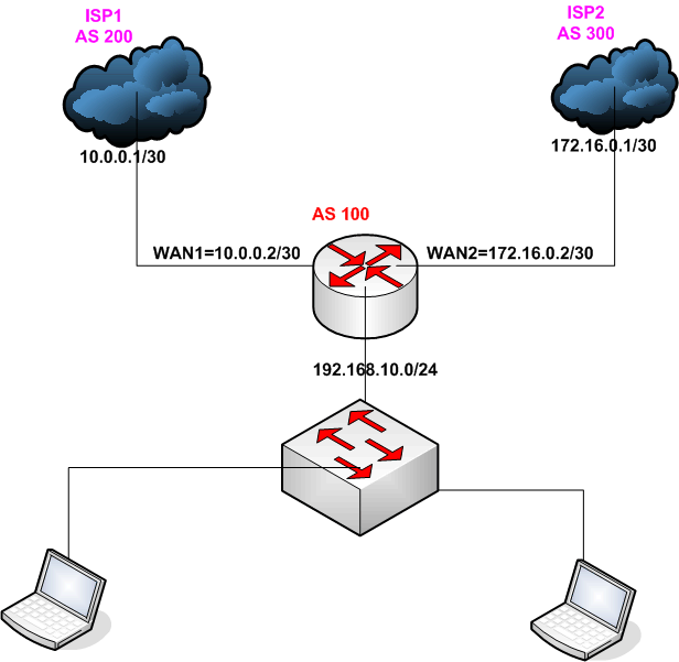
BGP Configuration Example using Mikrotik Router


This aricle introduce basic configuration about BGP, including ASN and E-BGP.
BGP use in TCP connection and using port 179,when connecting to the internet ,enterprise can use static route or a routing protocol name as Border Gateway Routing protocol(BGP).
See BGP Configuration video

Configure Basic ip address our mikrotik router


[admin@Laxmi]/ip address >            
add address=10.0.0.2/30 network=10.0.0.0 broadcast=10.0.0.3 interface=WAN1
add address=172.16.0.2/30 network=172.16.0.0 broadcast=172.16.0.3 interface=WAN2

Configure our AS number
[admin@Laxmi]/routing bgp instance>
set default as=100

Configure BGP Neighbor

[admin@Laxmi]/routing bgp peer>add name=ISP1 remote-address=10.0.0.1 remote-as=200
[admin@Laxmi]/routing bgp peer>add name=ISP2 remote-address=172.16.0.1 remote-as=300


Verification BGP peer

[admin@Laxmi] /routing bgp peer> print
Flags: X - disabled, E - established
 #   INSTANCE        REMOTE-ADDRESS                                 REMOTE-AS
 0 E default         10.0.0.1                                                              200    
 1 E default         172.16.0.1                                                    300


Network Advertisement Configuration

[admin@Laxmi]>
/routing bgp network
add network=192.168.10.0/24 synchronize=no


Outgoing and Incoming Filter Chain For ISP 1

[admin@Laxmi]>
/routing filter
add chain =ISP_1-out prefix=192.168.10.0/24 action=accept
add chain=ISP_1-out action=discard
[admin@Laxmi]>
/routing filter
add chain=ISP_1-in action=discard

Configure Outgoing and incoming Filter Chain For ISP 2
[admin@Laxmi]>
/routing filter
add chain =ISP_2-out prefix=192.168.10.0/24 action=accept set-bgp-prepend=5
[admin@Laxmi]>
/routing filter
add chain=ISP_2-in action=discard

[admin@Laxmi]>
/ip route
add gateway=10.0.0.1 check-gateway=ping
add gateway=172.16.0.1 check-gateway=ping distance=10


Remote Desktop L2TP VPN Server Configuration Using Mikrotik Router


Fig: L2TP over Ipsec VPN


L2TP used by service providers to provide VPN service over the internet.It is extension protocol of PPTP.L2TP dose no support encryption or confidentiality .L2TP packet including payload and header is sent  within UDP.L2TP have two endpoints LAC and LNS.
L2TP full meaning Layer 2 Tunneling Protocol,L2TP is Microsoft propitiatory,that can support Remote desktop VPN Server without any other VPN Software.It is easy to configure.


 Basic Ip Address Parameter Configuration:
[admin@LaxmiTani]/ip address> add address=103.7.248.206 interface=PUBLIC
[admin@LaxmiTani]/ip address> add address=192.168.1.1 interface=LOCAL

[admin@LaxmiTani]/ip pool> add name=VPNPOOL ranges=192.168.1.100-192.168.254


[admin@LaxmiTani]/ip firewall nat>
add chain=srcnat action=masquerade out-interface=PUBLIC

[admin@LaxmiTani]/ppp profile

add name="VPN" local-address=192.168.1.1 remote-address=VPNPOOL  dns-server=8.8.8.8,4.4.4.4


[admin@LaxmiTani]/interface l2tp-server>
            add disabled=no name=VPN
[admin@LaxmiTani]/interface l2tp-server server>
             set enabled=yes  

 /ppp secret>
[admin@LaxmiTani]/ppp secret> add name=test1 service=l2tp password=123 remote-address=VPNPOOL local-address=192.168.1.1
 
[admin@LaxmiTani]/interface Ethernet>set LOCAL arp=proxy-arp


Verification:
[admin@LaxmiTani] /ip address> print
Flags: X - disabled, I - invalid, D - dynamic
 #   ADDRESS            NETWORK         INTERFACE                               
 0   103.7.248.206/29   103.7.248.200   PUBLIC                                   
 1   192.168.1.1/24     192.168.1.0     LOCAL  


[admin@LaxmiTani] /ip pool> print

 # NAME                                                                                       RANGES                        
 0 VPNPOOL                                                                   192.168.1.100-192.168.1.254

[admin@LaxmiTani] /ip firewall nat> print
Flags: X - disabled, I - invalid, D - dynamic
 0   chain=srcnat action=masquerade out-interface=PUBLIC


[admin@LaxmiTani] /ppp profile> print
Flags: * - default
 0 * name="default" use-mpls=default use-compression=default use-vj-compression=default use-encryption=default
     only-one=default change-tcp-mss=yes

 1   name="VPN" local-address=192.168.1.1 remote-address=VPNPOOL use-mpls=default use-compression=default
     use-vj-compression=default use-encryption=default only-one=default change-tcp-mss=default dns-server=8.8.8.8,4.4.4.4

 2 * name="default-encryption" use-mpls=default use-compression=default use-vj-compression=default use-encryption=yes
     only-one=default change-tcp-mss=yes

[admin@LaxmiTani] /interface l2tp-server> print

[admin@LaxmiTani] /interface l2tp-server server> print

[admin@LaxmiTani] /ppp secret> print

[admin@LaxmiTani] /ip route> print
Flags: X - disabled, A - active, D - dynamic, C - connect, S - static, r - rip, b - bgp, o - ospf, m - mme,
B - blackhole, U - unreachable, P - prohibit
 #      DST-ADDRESS        PREF-SRC        GATEWAY            DISTANCE
 0   S  0.0.0.0/0                                            103.7.248.201                     1
 1 ADC  103.7.248.200/29   103.7.248.206   PUBLIC                           0
 2 ADC  192.168.1.0/24        192.168.1.1     LOCAL                             0


Mikrotik Router IP Sec Site to Site VPN Tunnel Configuration


VPN sometime called VPN Tunnel,gives the engineer  two remote site a way to send a packet between two 
site with private ip address through the internet,Ipsec site-to-site vpn tunnel used to allow the secure transmission between to remote site .VPN provides privacy,encryption and verification that the sender legitimate.  
In this scenario two remote office router are connected to internet and office workstation behind routers are NAT ed.Each office has its own local network  192.168.1.0/24 for  site1 and 10.10.10.0/24 for site 2.both remote site needs secure tunnel to local networks behind routers.


IP address Configuration for mikrotikroutersite1:

[laxmi@mikrotikroutersetup.blogspot.com]/ip address
Add address=172.16.1.2/30 interface=WAN
Add address=192.168.1.1/24 interface=LOCAL
/ip route                                                                                             
Add gateway=172.16.1.1
/ip firewall nat
Add chain=srcnet out-interface=WAN action=masquerade


Mikrotikroutersite2 configuration:
[laxmi@mikrotikroutersetup.blogspot.com]/ip address
Add address=172.16.100.2/30 interface=WAN
Add address=10.10.10.1/24 interface=LOCAL
/ip route
Add gateway=172.16.100.1
/ip firewall nat
Add chain=srcnet out-interface=WAN action=masquerade

Ip Sec Peer’s configuration:
We need to specify peers address and port and pre=shared-key  and other are default value.


MikrotikRoutersite1:
/ip  sec peer
Add address=172.16.100.2/32:500 auth-method=pre-shared-key secret=”123456”

MikrotikRoutersite2:
Add address=172.16.1.2/32:500 auth-method=pre-shared-key secret=”123456”

Policy and proposal Configuration:
We want to encrypt data coming from 10.10.10.0/24 to 192.168.1.0/24 and vice versa.

MikrotikrouterSite1:
/ip ipsec policy
Add src-address=10.10.10.0/24:any dst-address=192.168.1.0/24:any sa-src-address=172.16.1.2 sa-dst-address=172.16.100.2 tunnel=yes action=encrypt proposal-default

MikrotikrouterSite2:
Add src-address=192.168.1.0/24:any dst-address=10.10.10.0/24:any sa-src-address=172.16.100.2 sa-dst-address=172.16.1.2 tunnel=yes action=encrypt proposal-default

NAT Bypass Configuration:

MikrotikrouterSite1:
/ip firewall nat
Add chain=srcnet action=accept place-before=0 src=address=192.168.1.0/24 dst-address=10.10.10.0/24

Mikrotikroutersite2:
/ip firewall nat
Add chain=srcnet action=accept place-before=0 src=address=10.10.10.0/24 dst-address=192.168.1.0/24
Placed at the top of all other NAT rules and clear connection table from existing connection or restart the routers.   
                       
         See Video Mikrotik Router IP Sec Site to Site VPN Tunnel Configuration              


Howto give PING/ICMP high Priority use in Mikrotik Router firewall Configuration

This article provide  Howto give PING/ICMP high Priority use in  Mikrotik Router firewall configuration.


/ip firewall mangle
add chain=prerouting action=mark-connection new-connection-mark=ICMP_PING passthrough=yes protocol=icmp


add chain=prerouting action=mark-packet new-packet-mark=ICMP_PKT passthrough=no protocol=icmp connection-mark=ICMP_PING


/queue simple

  add name="ICMP" target-addresses=192.168.1.0/24
      interface=all parent=Total packet-marks=ICMP_PKT direction=both priority=1 queue=default-small/default-small
      limit-at=0/0 max-limit=2M/2M burst-limit=0/0 burst-threshold=0/0 burst-time=0s/0s total-queue=default-small


How to enable SNMP in Mikrotik Router


 This article provide how to monitoring mikrotik router traffic using SNMP.
[laxmi@Mikrotik]
  > /snmp
[laxmi@Mikrotik]
 /snmp > set enabled=yes contact=[YOURNAME] location=[LOCATION]

Next, set disable community public read access
[laxmi@Mikrotik]
 /snmp> community
[laxmi@Mikrotik]
/snmp community> print
# NAME ADDRESS SECURITY READ-ACCESS
0 public 0.0.0.0/0 none yes
[laxmi@Mikrotik]
 /snmp community> set public read-access=no
Add your community name and specify access ip address
[laxmi@Mikrotik]
/snmp community> add name=network address=172.16.10.0/24
[laxmi@Mikrotik]
 /snmp community> print
0 public 0.0.0.0/0 none no
1 network 192.1681.0/24 none no
[laxmi@Mikrotik]
/snmp community> set network read-access=yes